
Only SFNs Deliver ATSC 3.0 Everywhere: Turning Broadcast Theory into Nationwide Reality
Louis Libin, ONE Media
Abstract – The introduction of ATSC 3.0 as a television broadcast standard has significantly expanded the capabilities available to broadcasters. While these new features open the door for new business opportunities, they can also force difficult choices in the allocation of the limited data capacity available in the broadcast stream. The use of single frequency networks (SFNs) can improve this situation in many cases, but at the cost of increased network complexity. For many new business models being considered, the adoption of SFN will be the only way to provide the kind of ubiquitous signal coverage demanded by customers. This paper outlines the why, when, and how of SFN deployment at a high level. While there are many detailed technical tradeoffs in an SFN network, sometimes the more difficult factors in SFN deployments are the physical design and deployment aspects of the network. This paper focuses on the physical aspects of SFN networks.
Introduction
The ATSC 3.0 standard supports a broad range of features including advanced error correction (LDPC/BCH), scalable modulation (from QPSK to 4096-QAM), and adjustable robustness profiles for different services. This means a broadcaster can design a network to simultaneously support ultra-reliable mobile reception and high-throughput fixed reception, all on the same RF channel. But doing so requires tradeoffs: higher robustness generally means lower throughput, while pushing spectral efficiency can limit service range or resilience. One of the key features of ATSC 3.0 is support for SFNs. SFNs allow for multiple synchronized transmitters to operate on the same frequency to improve signal strength in targeted areas. ATSC 3.0 was designed from the ground up with SFNs in mind and includes native interfaces and mechanisms to support seamless SFN integration.
In the implementation of ATSC 3.0 services, tradeoffs must consider real-world factors such as terrain, population density, service mix, regulatory limits, and business goals. Some stations may prioritize maximizing reach for public safety applications; others may target data-casting or commercial data streams to vehicles or homes. A significant and sometimes difficult decision is whether to include an SFN network as part of the implementation. The difficulty of SFN deployments is usually the complexity of the SFN design and deployment itself, rather than the signal quality benefits as these are not difficult to simulate.
For many services, implementing an SFN will be mandatory to provide the level of robust connectivity demanded by today’s customers. Many potential new business opportunities made available by ATSC 3.0 require getting signal to customers where they are, and on a variety of receiver devices. These types of services are very different from the traditional broadcast service and require an entirely different mindset when thinking about network design. Early Cellular networks had the advantage of being the first to develop ubiquitous coverage and were able to grow and improve over time. New ATSC 3.0 services will not have that advantage and will be immediately compared to the existing services available via cellular and widely available WiFi networks which have had many years of both technical advancement and network buildout to deliver robust services.
SFN design is a well-studied and often implemented broadcast architecture. There are several reports and implementation guides available that provide an overview of SFN implementation. Report ITU-R BT.2386-5 [1] gives a broad outline of SFN architecture including the use of ATSC 3.0 in SFN networks. The TV Network Planning: SFN Design Guidelines, GAP Fillers, SFN’s Applications [2] also provides some high-level context around network planning. There are several papers available for SFN planning for DVB-T2 systems including several large systems developed for Europe. While some of the parameters for ATSC 3.0 are different than for DVB-T2, many of the high-level planning approaches are the same. Agnes Ligeti’s Single Frequency Network Planning, [3] provides some insight from planning a large DVB-T2 SFN system. The EBU technical report TR-016 [4] provides some context for some of the benefits and limitations of SFN systems.
One example of a large SFN deployment was MediaFLO which operated a continent-scale, tightly synchronized broadcast architecture across hundreds of transmission sites. MediaFLO’s success in maintaining timing alignment across a large number of synchronized transmitters established that national-scale SFN synchronization is technically achievable. Using GPS-based timing and carefully managed guard intervals, the system delivered stable OFDM performance even across long-haul backhaul paths. ATSC 3.0 inherits these principles and improves on them substantially with configurable numerologies, enhanced robustness under multipath, and more efficient physical-layer overhead structures, making it even better suited for complex propagation environments.
The Why of SFN Deployment
During the analog broadcast era, the focus was on delivering a single program to the largest audience without interfering with other broadcast signals in nearby cities. This involved a complex process by which spectrum regulatory bodies allocated frequencies and transmit powers to broadcasters to maximize the use of the available broadcast spectrum. Given an assigned transmit power, a service area was defined by the reliability of the transmitted signal. This involved many assumptions around the size, type and height at which antennas would be mounted. These assumptions did not always fit well with many consumers who could not use a large outdoor antenna like apartment buildings, or where the signal was blocked due to natural or man-made obstructions. Since the signals were analog, consumers were often left with watching a program with poor signal quality due to either low signal levels, ghosting from signal reflections or both.
In the next evolution of the broadcast signal, the analog signal was replaced with a digital signal. While the general methodology of assigning frequencies and transmit powers was the same, moving to a digital signal improved the experience for the consumer. If the signal level exceeded the required C/N (Carrier to Noise) threshold, the quality of the video/audio signal would be near perfect. Since the signal was a digital data stream, broadcasters could also allocate the data capacity amongst several “virtual” program channels. This gave broadcasters a first taste of data capacity allocation where tradeoffs between the number of “virtual” channels and the video quality of the channels was required. While multiple data streams with different content could be allocated on a single channel, all of the data streams operated at the same C/N operating point (i.e., there was only one modulation/error correction coding scheme for all data streams).
Data Capacity Tradeoffs
With the introduction of ATSC 3.0, many new features have become available including a wide range of C/N operating points; the addition of Physical Layer Pipes (PLP)s, which allow individual streams within the overall signal to operate at different C/N operating points; features to enhance mobile reception; and many others. Sometimes it can seem that the options for allocating the data capacity of a channel become overwhelming. The tradeoffs become not only technical but intertwined with business use cases.
The ATSC 3.0 Physical layer standard [5] and usage guidelines [6] give a detailed description of the available combinations of modulation, error correction coding, data rate, and operating point. Figure 1 shows the available ATSC 3.0 modulation and error correction settings in terms of C/N vs data capacity for an ATSC 3.0 system. However, for some use cases that require a very robust modulation and error correction scheme, there can be a steep price to pay in terms of data capacity. For example, if only 20 dB of C/N is needed, the ATSC 3.0 channel can carry more than 30 MBits/sec of information. However, if a use case requires 5 dB SNR, then the channel will be able to carry less than 10 MBits/sec.
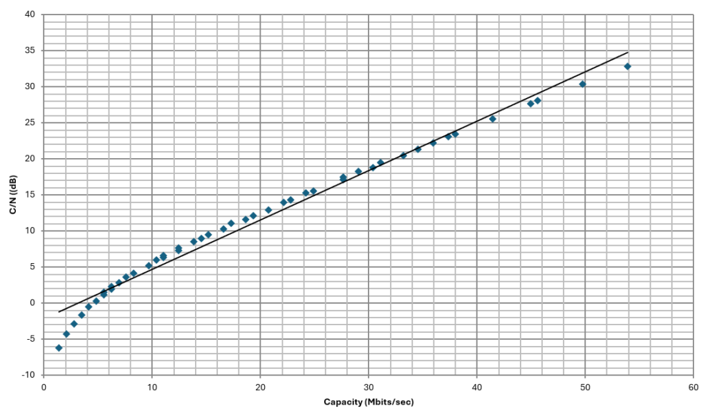
As broadcasters expand beyond traditional video programming and want to add other services, allocating the available capacity on a channel may become problematic. One of the best methods to alleviate the data capacity challenge is to raise the signal level around the areas where the service will be received. This may be a localized area for some use cases or a broader area for others. If for example, the signal level can be raised by 10 dB in the use case reception area, the capacity tradeoff is much less drastic. This data capacity tradeoff vs the cost of SFN deployment is one of the key decisions when deploying a new use case.
Business Use Case Requirements
When determining traditional television broadcast coverage areas, various models have been used to forecast signal strength and coverage percentages to indicate whether an area is “covered”. For example, 50/90 propagation curves, where 50% of locations exceed the required signal level for reception 90% of the time. This type of coverage mentality has worked in the past for television broadcasting for several reasons. For one, customers have gotten used to the idea that they may or may not be able to receive a TV signal at their home and that is just the way it is. If they can’t get over the air TV, they can turn to cable, satellite, or streaming. Broadcasters have only one tower and a set of FCC rules to follow, so there is not much they can do to improve the coverage.
With the introduction of ATSC 3.0, the TV broadcast industry can branch out from their current business models into new revenue opportunities. However, not all new business use cases will have the same coverage paradigm as a typical broadcast use case. Each use case has different reception needs and expectations. Three of the more general use cases are summarized below.
- Existing coverage use case where customers will either get service or not. There may be some attempts to improve the existing coverage using SFNs, but the customer expectations are that the service may be spotty in some areas. This could cover some business models where professional antennas could be installed to support a low number of high value customers or services where it is not critical to have continuous coverage.
- Spot coverage use cases where SFN transmitters could be targeted at isolated high value customers or areas. For example, adding a small SFN to supply coverage to a stadium or convention center for specific events.
- Ubiquitous coverage use cases where customers are possibly mobile and expect reliable coverage as they move around. Examples would be use cases where reception is required for phones, tablets, or vehicles. This presents the largest revenue opportunity due to the high number of customers, but also has the highest deployment costs as ubiquitous coverage may require a high number of SFN transmitters.
The following sections describe some broad use cases that may be encountered by broadcasters as they venture into new business opportunities using the capabilities of ATSC 3.0.
Improved Broadcast TV Coverage
For this use case, the expected receive signal levels are defined by a national regulatory body for TV reception. This is the traditional use case for broadcast video programming, and its goal is simply to provide quality reception within the defined coverage area. Due to natural or man-made obstructions, there may be pockets within the coverage area that do not receive an adequate signal level for reception.
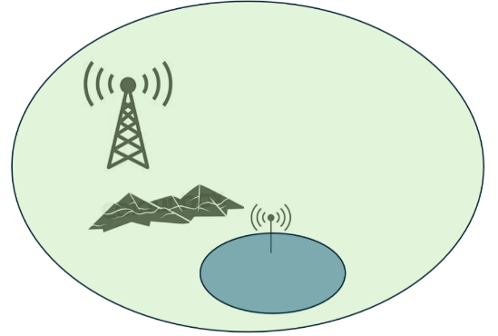
This type of coverage is still guided by the assumptions defining over-the-air TV coverage which typically includes the use of a large outdoor directional antenna mounted at 10m or more. In many cases, coverage holes exist in the targeted coverage area and are caused by the shadows of large mountains or deep valleys which may cover significant portions of the coverage area or significant portions of the covered population. An SFN can be used to improve coverage in these types of areas and may consist of a single large SFN installation with a relatively high power (e.g., 5 KW) or several smaller SFNs within the shadowed area. Directional transmit antennas can be used to direct the additional SFN signal power in the shadowed area to maximize the effects of the SFN transmitter.
Highway Coverage
This use case provides services to customers in vehicles. This may be data such as traffic information, mobile entertainment, or smart car SW updates. This type of SFN deployment targets a specific narrow corridor. The SFNs for this type of deployment do not have to cover a large area and can use directional antennas to target the corridor. However, continuous coverage over the entire length of the highway may require an SFN tower every few kilometers depending on the terrain.
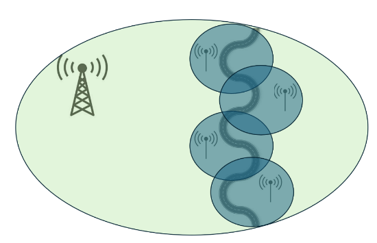
The size of the SFNs would typically be lower power (20-100W) and therefore may be small self-contained units mounted to existing cellular towers.
Small Targeted Venues
This use case targets very small areas such as stadiums, convention centers, malls, or other relatively small, high-density locations. These areas are small in scale (< 1000 m) but may have lots of internal building obstructions such as different floors and rooms separated by thick concrete structures. These environments are similar to those encountered when developing indoor Wi-Fi networks. The individual SFN transmitters only need low power, but there need to be many SFN locations to adequately cover the venue. The power levels will likely be <10W, and the venues will likely already have access to high-speed connectivity to provide the needed data sources.
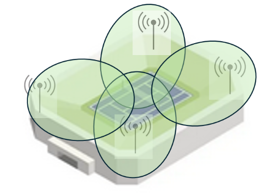
The challenge will be locating the SFN transmitters and adjusting their timing to avoid unwanted high self-interference areas caused by overlapping transmitters. High accuracy clocks may also be an issue as there may not be access to GPS signals at the installation sites. This may require alternatives to GPS clocks to provide timing for SFN transmitter timing alignment.
Portable Ubiquitous Coverage
This use case targets the same or nearly the same coverage as cellular systems today. This includes not only outdoor but also indoor coverage. According to the Broadcast Industry Guideline Specifications for Next Gen TV SFN Design and Implementation [7] the signal level difference between the normal FCC defined outdoor coverage and indoor coverage may be more than 40dB. The current broadcast methodology to access coverage uses reception percentages like 50/90 curves, which assumes the signal will sometimes be received and other times it will not.
Existing cellular customers expect to receive service all the time, no matter where they are. This means even small areas that lack signal due to buildings or other obstructions must be filled in with SFNs. To provide ubiquitous coverage, almost all areas will need to receive signals from several SFN transmitters located in different directions. This allows someone to move from one side of a building to another and maintain a quality signal level without ever having the signal go below the reception threshold. This type of coverage is expected to need a large number of SFNs including a mix of high power and low power transmitters. While covering an entire city with SFN transmitters can be costly, some cities are experimenting with SFN systems [8] to provide services citywide. Figure 5 shows an example of the 30+ SFN sites that might be required in a moderate sized city.
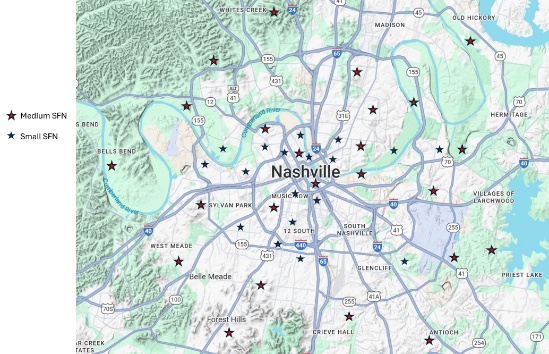
This type of SFN coverage will need to use all the tools in the toolkit. This includes several large 5kW+ SFN locations, many localized 20-100W SFN locations to cover individual streets and neighborhoods, and many small localized <10W SFN locations to cover specific high-density locations. This will be similar to a cellular carrier deployment and will require an ongoing effort over time to continuously improve coverage with additional SFN installations as new neighborhoods arise and business use cases change. This requires a large investment in time, effort, and capital, but gaining ubiquitous coverage opens up the most business opportunities by targeting customers directly, instead of targeting only business to business use cases through targeted SFN deployments.
Large Overlapping Coverage for a State, Province or Country
This use case targets large areas such as states, provinces, or even entire countries. In this example, there will be geographic obstacles to overcome as well as political borders where different spectrum regulatory rules exist. The SFN will need to be designed so that it meets the required signal levels at the political borders. This may require the SFNs to have directional antennas in addition to careful placement of transmission towers to maximize the signal level within the area of interest, while minimizing the signal levels that will cross political borders.
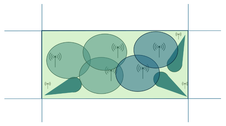
This type of SFN deployment will likely use higher power SFNs (>10kW) for many of the sites within the interior of the targeted coverage area and lower power SFNs at the edges of the coverage area.
SFN Planning
Each use case will need to build an appropriate link budget to determine the signal level that is required at the receiver antenna to meet the needs of the targeted customers. For a traditional broadcast use case, the signal level was largely determined based on FCC planning factors, including the use of a large outdoor antenna along with a set of statistical reception predictions.
The traditional FCC planning factors aren’t expected to be useful in determining the required signal levels for many new use cases. When calculating the required signal levels, the following are some additional factors that should be considered for any new use cases:
- Receiving Antenna
- What is the receiving antenna gain?
- What is the expected height of the receiving antenna? (For handheld devices is it roughly 1.5 meters from the ground?)
- Reception Locations
- Is the signal expected to be received indoors?
- Is the signal expected to be received deep indoors? (Does the signal need to travel through multiple walls?)
- Is the receiver mobile, either in a vehicle or handheld?
- What are the expectations of customers in terms of reception?
- Is coverage comparable to cell coverage expected?
- Does the use case need continuous reception (e.g., live video) or is it a background reception task that can be interrupted (e.g., to download software updates)?
Determining Coverage
The coverage area needed for a specific use case is largely determined by the use case itself. For example, a small, isolated area such as an event venue will only require a small coverage area, while a state or country will require a large one. In both cases, there are tradeoffs between the cost of adding SFN sites and the signal quality within the coverage area.
When designing the coverage area, there are several tradeoffs including the number of SFN sites, the power level of each site, the selection of a modulation and coding scheme, and the quality of the coverage. In addition, there may be regulatory requirements that limit the signal levels such as country borders or defined coverage areas. Optimizing these tradeoffs requires an iterative process where each component is modified and the resulting coverage area assessed. The goal of each iteration is to move towards the optimum cost/performance tradeoff that best satisfies the use case.
Planners must use Digital Terrain Models (DTMs) and population heatmaps to understand where signal “fill-ins” are needed, and where excess overlapping could cause destructive interference. There are several commercially available software packages that can be used to model SFN transmitter layouts. Many of these software packages also include population data as well as clutter data that can give a detailed map of the expected population and area coverage. Many of these tools can also produce interference maps and help guide the development of antenna beam shapes to minimize interference.
Since the ATSC 3.0 system may be simultaneously providing several services, multiple coverage maps may be required to gain a complete picture of the expected system performance.
FCC Rules for SFNs
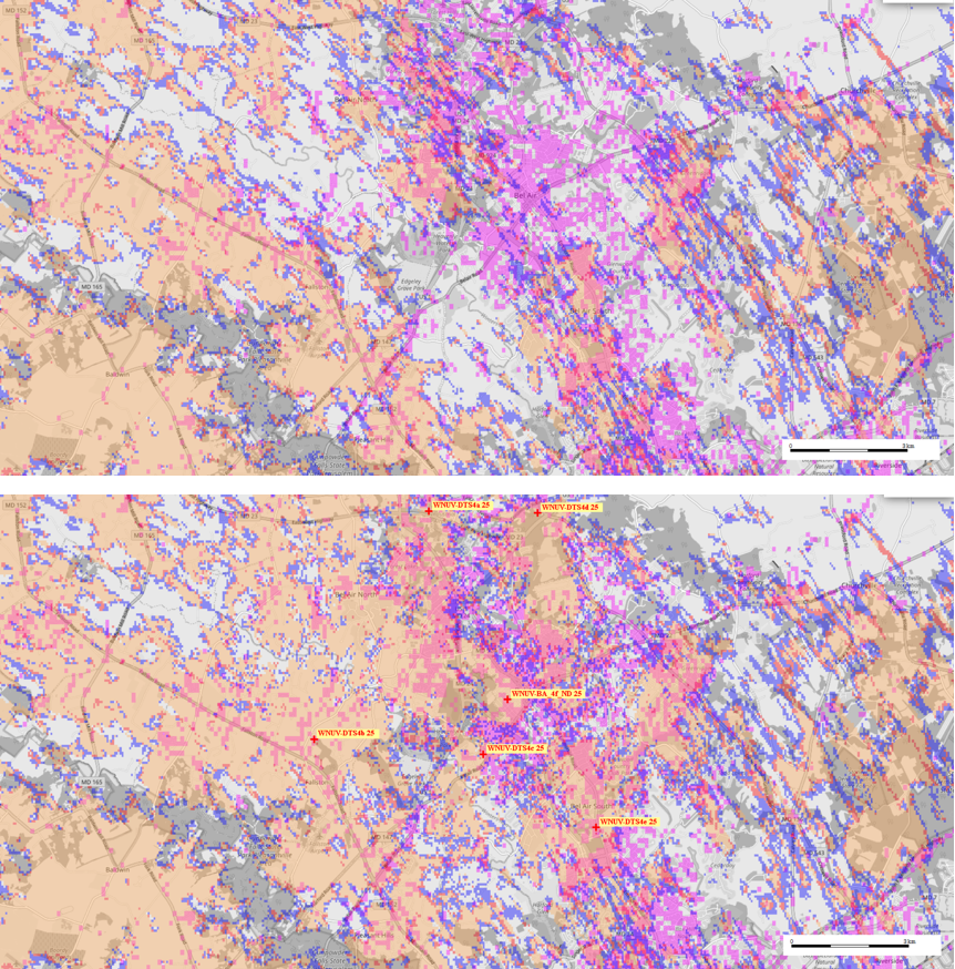
For SFNs being deployed in the U.S., the FCC has rules that must be followed to limit the interference to other broadcast signals. The FCC rules for Distributed Transmission Systems (DTS) allow TV broadcasters to use multiple low-power transmitters on the same channel to create a stronger, more uniform signal.
The subjective “minimal amount” standard for signal spillover was updated in 2021 with clear, technical standards to provide regulatory certainty for DTS deployment, especially for ATSC 3.0. These rules provide broadcasters with flexibility to enhance coverage and reception, particularly for mobile and indoor viewing without unnecessarily interfering with other stations.
Transmitter Site Selection
Once the desired coverage areas and signal levels are determined, the process of selecting optimal sites for SFN transmitters can begin. This is usually a highly iterative process where the ideal simulated locations meet the real-world restrictions of installing transmitters. This can be a lengthy process as many potential locations may require business negotiations with the site owners as well as navigating local regulations around transmitter sites. The process generally follows these steps:
- Potential transmitter locations are identified based on the coverage area. This may be existing towers, tall buildings, or utility poles for small transmitters. For spot coverage, such as arenas, this involves searching blueprints, or the physical site to determine the available locations for transmitters.
- Find a set of locations that satisfy the coverage requirements, based on simulated coverage areas, desired signal levels, and possible transmitter locations. This does not mean it meets 100% of the desired coverage. There will nearly always be some areas that cannot be covered by a reasonable number of SFN transmitters and available locations, but the best match possible should be the starting point.
- Survey the selected transmitter sites to ensure there is available space for a new transmitter, the space meets the transmitter needs (e.g., data, power, climate control), and a reasonable business agreement can be obtained for the site.
- In many if not most cases, one or more of the selected locations will not be available. This requires iterating the plan by moving some of the transmitters to alternative sites and/or changing from a high power to several lower power transmitters which have lower install requirements. The process then returns to step 2 and a number of iterations are made until an acceptable solution is found.
Transmitter Size and Power Classes
In SFN deployments, transmitters come in a variety of sizes and power levels, each suited to different roles within the network. These range from small “fill-in” nodes to full-power broadcast towers. Selecting the right mix of transmitter sizes is essential to ensure consistent, high-quality reception across varied terrain and population densities.
| Transmitter Class | ERP Range | Typical Range | Common Use Cases | Deployment Notes |
| Micro | ≤1W | < 1 kilometer | Indoor coverage, transit stations, smart poles, stadiums | Easy to install; often mounted on rooftops or lampposts |
| Small | 1 – 100W | 1–5 kilometers | Neighborhoods, small towns, urban edge zones | Ideal for gap-filling in tough terrain |
| Medium | 100W – 5kW | 5–10 kilometers | Suburban rings, mid-sized cities, rural valleys | Balances reach and precision; most common SFN nodes |
| Large (Anchor) | ≥5kW | 10+ kilometers | Major metro areas, market-wide coverage | Often a major site; requires careful SFN timing tuning |
Site Construction
Construction of SFN sites can range from a major endeavor where towers are constructed from scratch to much smaller projects where a micro-transmitter is plugged into a wall and set on a shelf. The rules governing construction projects vary widely depending on local building codes and permit processes. In any case, there are a few common areas that should be addressed for any installation.
- What environmental requirements are needed?
- Indoor vs Outdoor installation
- Passive or Active cooling
- Operational temperature limits (e.g., air conditioned room)
- What are the power requirements for the transmitter?
- Voltage levels
- Power Consumption
- What high speed data sources are available?
- One-way or bi-directional data connection
- Reliability of the data connection
- What antenna is needed?
- Antenna size
- Antenna mounting including expected wind loading
- What local permits are needed for construction?
Each installation will have a unique set of challenges. For larger installations, such as building a new tower or adding a large transmitter to the top of a building, there may be extensive local permitting and inspections required for the construction. In many cases the permitting process can take an extended time period, so appropriate planning needs to take this into account. Local contractors with experience of the local permitting process can help expedite the process.
Gaining access to power and data connections can also be a roadblock to a new construction. Higher power SFN transmitters may require new power lines to be run, and backup power may be required for some installations.
For larger transmitters, it is often easier to use existing towers which already have power and data connections available. There may still need to be some site construction to house the transmitter, but many existing tower sites are built with new installations in mind. They may also provide the power and data connections, and the space on the existing tower for mounting the antenna. While using an existing tower may speed up the installation process, there are some drawbacks including a recurring rental cost and the fact that the tower location may not be optimal in terms of the SFN coverage it provides.
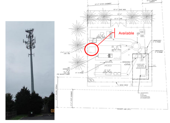
For smaller transmitters on utility poles or the sides of buildings, there are a different set of processes that must be followed. Utility poles may be owned by a government organization or a local utility. Agreements will need to be in place before utilizing them. When mounting on the side of buildings, local permitting may be required along with agreements with the building owners.
For localized coverage such as a stadium, convention center, or shopping mall, an agreement with the venue owner will be needed along with surveys of the site to determine the best locations for the mini or micro transmitters. Each location will need access to power and data connections. The power needed from these small types of transmitters can usually be provided by AC outlets already available. Data connections could be more difficult to access and may limit the locations available for installation. For these types of indoor installations, getting access to accurate timing signals may also be problematic since GPS signals may not be available to many of the transmitter sites. Alternative timing signals may be needed if GPS is not available.
Data Connections
Each transmitter in an SFN network outputs the same signal over the air and follows specific timing requirements to allow the overlapping signals to be received correctly. The data to be transmitted along with instructions on how and when to send the data needs to be communicated to all of the SFN transmitters in a timely manner. The ATSC standard defines the protocol for getting data to an SFN transmitter in A/324 Scheduler/Studio to Transmitter Link [9]. This standard provides a protocol for communicating data, but not the physical medium over which the data is communicated. This allows the physical medium to vary depending on the circumstance and may be different even between SFN transmitters in the same network.
Getting the data to each of the SFN installations is one of the most difficult problems for SFN installations. The most common techniques are to use fiber or a dedicated microwave link. Fiber may not be practical if it’s not already installed at a site because running new fiber may be prohibitive in cost and time. Microwave can be used but requires licensing and planning and may not be practical when a large number of SFNs are deployed. Two promising areas for data distribution are in-band distribution and satellite.
Testing
Once an SFN is deployed, it is critical to test the system to ensure that it meets the intended reception goals. An SFN system is more complex than a single transmitter system and there are several additional ways that an SFN can be misconfigured. For example, each SFN transmitter may need different timing corrections applied to ensure that the combination of the signals meet the guard interval requirement within the reception area of interest. If these delays are set incorrectly, or the time reference is incorrect at one or more SFN sites then large areas will have poor reception. Also, some SFN transmitters may use directional antennas to maximize the signal in specific areas or minimize regulatory interference limits. If one or more directional antennas are mis-aligned, this can cause the actual signal levels to differ from what is expected.
For ATSC 3.0 testing in general, the A/326: ATSC 3.0 Field Test Plan [10] is a good source of information. It provides guidelines and procedures for testing several common use cases. One of the largest factors in testing a system is whether the system is currently in-service, or a new green field system. For new green field systems, each SFN transmitter can be turned on in isolation, and the resulting signal levels measured and compared with the predicted signal levels. Then to adjust the timing between the transmitters, different sets of transmitters can be activated together and the timing compared using the transmitter TxID (Transmitter ID) signatures.
Usually, a system is already active with at least a main transmitter running and maybe one or more SFN transmitters active. In this situation, there are customers using the service and the existing transmitters cannot be turned off. Extra care must be taken to avoid disruptions, such as testing the system overnight, or at a lower power than the final power.
The test plan will be determined by the use cases that lead to the installation. For example, if the use case is to deliver data to a group of commercial locations, then the test plan would focus on testing the signal characteristics at those locations. If it is to provide signal along a highway, then the test plan would involve a series of drive tests. However, in general, SFN testing would have the same basic features.
SFN Field trials have been performed for several use cases including mobile and stationary reception in different terrains. Looking at the results of these trials can assist in designing a field test, and mitigating the problems that might be encountered. Some good examples can be found in [11], [12], and [13].
SFN Monitoring
Once an SFN system has been installed, it will need to be monitored for proper operation. This ensures the system is providing the expected end-user services, and that the signal levels meet regulatory requirements. There are several types of signal monitoring to check the status of the system.
The simplest is to monitor the health of the transmitters using built in monitoring capabilities. Generally, transmitters monitor several parameters such as data connectivity, transmit power levels, thermal conditions, timing accuracy, etc. This information can usually be accessed remotely if the transmitter has access to remote networking. In some cases, the transmitter software can be set to trigger an alarm if operational conditions exceed set parameters. This type of monitoring is the first line of defense against incorrect SFN system operation.
Several companies provide higher level systems to monitor SFN systems with a large numbers of transmitters. These systems consolidating the information into concise outputs so it is easy to determine if one transmitter out of many is having a problem.
While transmitter health monitoring is very effective, there are a few parameters that are difficult to monitor at individual transmitters. One of these is the relative time delay between transmitters. If a transmitter has a problem where its transmission delay does not match the expected delay it can cause reception problems. This is hard for a transmitter itself to detect, as it is the relative delay between transmitters that is important.
It is also hard to detect if an antenna gets damaged or mis-aligned unless the damage is extensive and the antenna becomes disconnected from the transmitter. Monitoring receivers placed where they can receive signals from several SFN transmitters can check for these issues. The receivers periodically transmit the TxID to check relative signal levels and timing between them. They are connected via a remote network to provide information back to a common monitoring point. Many systems allow for timing and signal level thresholds to be set so that alarms are generated when measurements exceed the expected limits.
The costs of installing and maintain monitoring receivers may exceed the expected benefits in some instances, like when a service is delivered to a small number of high value customers. In this case, there may be some service monitoring at the customer premise, or a customer might just call to report an outage.
When there is a large service area and a large customer base, installing monitoring receivers may be worth the effort. The number of monitoring receivers should be enough to provide adequate coverage while not so many that the monitoring system itself becomes a reliability concern.
Summary
ATSC 3.0 provides the opportunity and tools to allow for a robust and innovative set of new business models. Many of these new business models will require the use of SFN transmitters to provide robust coverage and customer satisfaction. For SFN deployment, the major hurdles are usually not technical in nature, but in the physical deployment of the network itself. These aspects need to be carefully analyzed to ensure that the deployment meets the expected performance level and continues to provide value to the business and customer alike.
References
- “Report ITU-R BT.2386-5 – Digital terrestrial broadcasting: Design and implementation of single frequency networks (SFN),” 03/2024, International Telecommunication Union, Geneva, Switzerland.
- Steven Rossiter, “GATESAIR TV NETWORK PLANNING : SFN Design Guidelines, GAP Fillers, SFN’S Applications,” GatesAIR, Mason, OH, https://www.gatesairuniversity.com/documents/gatesairconnectvirtualevents- tvnetworkplanning-sfn-05142020.pdf
- Agnes Ligeti, “Single Frequency Network Planning,” Dissertation submitted to the KTH Royal Institute of Technology, Stockholm, Sweden, 1999.
- ”TR-016 Benefits and Limitations of Single Frequency Networks (SFN) for DTT”, 10/2012, European Broadcasting Union, Le Grand-Saconnex, Switzerland.
- “ATSC Standard: Physical Layer Protocol,” Doc. A/322:2024-9, Advanced Television Systems Committee, Washington, DC, 3 September 2024.
- “ATSC Standard : Guidelines for the Physical Layer Protocol,” Doc. A/327:2025-05, Advanced Television Systems Committee, Washington, DC, 3 February 2025. ATSC: “ATSC Standard: Scheduler / Studio to Transmitter Link,” Doc. A/324:2024-04, Advanced Television Systems Committee, Washington, DC, 3 April 2024.
- “Broadcast Industry Guideline Specifications for Next Gen TV SFN Design and Implementation,” Meintel, Sgrignoli, and Wallace, 2021
- SMITHANDFISHER, “How Single Frequency Netowrk is Shaping the Next Generation of Smart Cities”, May, 2025.
- “ATSC Standard: Scheduler / Studio to Transmitter Link,” Doc. A/324:2024-04, Advanced Television Systems Committee, Washington, DC, 3 April 2024.
- “ATSC 3.0 Field Test Plan,” Doc. A/326:2024-04, Advanced Television Systems Committee, Washington, DC, 3 April 2024.
- Phil Kurz, “NextGen TV: Phoenix Test of 3.0 SFN Demonstrates Improved Signal Robustness,” 6/2021, tvtech.
- Sunhyoung Kwon, “ATSC 3.0 Direct-to-Vehicle (D2V) Field Evaluatioon Results,”, 1/2025, ETRI.
- IEEE: S. Ahn, B.-M. Lim, S. Kwon, S. Jeon, X. Wang, and S.-I. Park, “Diversity receiver for ATSC 3.0-in-vehicle: Design and field evaluation in metropolitan SFN,” IEEE Trans. Broadcast., vol. 70, no. 2, pp. 367–381, Jun. 2024.